
EMI Filter Recommendations: Top Picks for Clean Power and Reduced Noise
2026-10-15
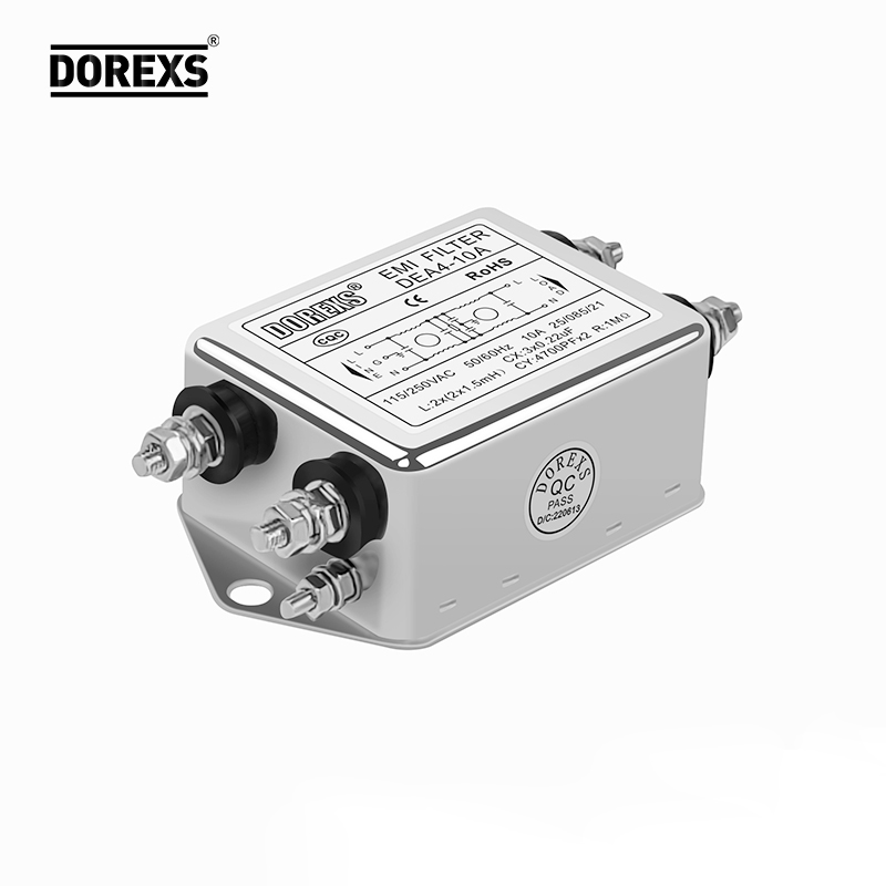
If you've ever spent an afternoon chasing down intermittent resets or unexplained signal glitches, you already know clean power isn't a luxury—it's the foundation. The culprit often hides in plain sight: conducted EMI riding along your power lines. Rather than adding more shielding or ferrites and hoping for the best, choosing the right EMI filter from the start saves hours of debugging. In this guide, we break down our top recommendations for reliable filtering that actually reduces noise and keeps your power rails stable. Whether you're working on a compact design or a high-power industrial system, there's an option here that fits. And for filters built to handle real-world conditions without the guesswork, DOREXS is a name worth knowing. Let's get your power clean—so your circuits can do what they're supposed to do.
Why Most Setups Still Suffer From Conducted Noise
The usual culprit isn't a missing ferrite bead or an undersized capacitor, though those get blamed often. Most conducted noise problems trace back to the return path. When high-frequency currents from a switching converter or digital logic don't have a low-inductance route back to the source, they spread across the board's ground plane and find their way into I/O cables. That turns a local issue into a system-wide one, and the noise you measure at the power input is often just a symptom of a much messier current loop.
Another overlooked factor is that filters are rarely designed for the actual impedance they will see. A capacitor across the line only works well if the source and load impedances are low at the troublesome frequencies. Once the converter's input impedance rises due to regulation or the cable inductance dominates, that capacitor becomes far less effective. Designers also tend to place common-mode chokes after the point where the noise has already coupled onto the cable shield, which means the choke is treating the wound after the patient has bled out.
Finally, ground loops created by multiple chassis connections or poorly bonded cable shields can convert common-mode noise into differential noise right at the sensitive circuitry. A setup may look clean on a bench with a floating scope, but when installed with real earth connections, the noise appears. This is why so many devices pass lab tests yet still misbehave in the field; the test setup doesn't replicate the actual conducted noise environment.
Filter Topologies Worth More Than Their Spec Sheet
A filter's stopband rejection or passband flatness looks clean on paper, but the real test happens when you build it with 5% resistors and a budget op-amp. Some topologies, like the Sallen-Key, hide their quirks behind simple math - a little interaction between gain and Q that only shows up when you tweak one component. Others, like the multiple feedback band-pass, dish out inverted output and low input impedance that can surprise you mid-design. That's the stuff no spec sheet bothers to list.
Take the state-variable filter. Three op-amps seem excessive until you realize you can tune cutoff and Q independently without recalculating every passive part. In a real lab, that means swapping one resistor to shift frequency, not re-spinning a board. Its high-pass, band-pass, and low-pass outputs come free, which turns a supposedly single-purpose block into a multi-mode toolbox. On paper it's just higher power draw and more components; on the bench it's the topology that saves you from a drawer full of half-populated prototypes.
Then there's the overlooked GIC-based filter or the twin-T with bootstrapping - rarely the headline choice, yet they shine when you need decent performance from a single supply or avoid precision capacitors. The lesson isn't that one topology wins; it's that the spec sheet is a starting point. The hidden value often lives in how gracefully a circuit degrades when real parts drift, and that only shows up after you've built a few.
Matching Attenuation to Your Noise Profile
A high NRR number on the package rarely tells you how a protector will perform in your specific workplace. The actual risk comes from the frequencies that dominate your noise exposure, not the overall loudness. A grinder screams in the 4 kHz to 8 kHz range, while a diesel engine thumps below 500 Hz. If your earplugs attenuate mostly high frequencies, they'll do little against that low-end rumble, no matter how impressive the single-number rating looks.
Start by mapping your noise, either with a dosimeter that captures octave-band data or by checking the manufacturer's sound survey. Then compare that profile against the attenuation tables printed on the protector's technical sheet. Look for a curve that dips where your noise peaks, not just a flat reduction across the board. For mixed exposures, you may need a combination—like a deeply inserted foam plug under a high-attenuation muff—to cover both ends of the spectrum without creating a false sense of security.
There's also a practical trade-off. Over-attenuating the frequencies where speech lives makes it harder to hear alarms, warnings, or a coworker's shout, which pushes people to remove their protection. A better match often means slightly less reduction in the 500 Hz to 2 kHz band and much more where the hazard actually sits. Real-world fit varies, so test the seal and re-check your attenuation whenever the noise source or working distance changes.
Top Picks for Benchtop, Rack, and Field Use
Bench space gets fought over quickly, so a benchtop pick needs to be compact without cutting corners on measurement depth. The 34461A from Keysight still earns its spot because the display is bright and the trend chart feels like a mini scope. For mixed-signal debugging, the Rigol MSO5000 series gives you four analog channels and 16 digital lines in a footprint that doesn't eat the whole shelf.
Rack-mount instruments are about density and remote control. A 2U power supply like the Keithley 2230G-30-6 fits three isolated channels into a small vertical slice, and the front-panel binding posts are spaced well enough for stacked banana plugs. If you're building an automated test rack, the Tektronix DMM6500 with a rear-panel trigger link keeps timing tight without a mess of BNC cables.
For field work, the pick leans toward one-handed operation and a screen you can read in daylight. The Fluke 87V Max is still the default because it survives drops and has a backlit display that doesn't wash out. For more than just voltage checks, the PicoScope 4444 rides in a laptop bag and gives you four differential channels, so you can probe industrial sensors without lugging a bench scope around.
Grounding and Placement Habits That Make or Break Results
Return currents don't follow the path you'd expect—they follow the lowest inductance route, which usually means hugging the signal trace. When a ground plane gets sliced by a slot or a poorly placed via field, that return current detours and you end up with common-mode noise and radiated emissions. A habit that saves boards: drop a ground via next to every signal via and keep the plane unbroken under clocks and high-speed lines.
Placement order matters more than final location fixes. If you treat decoupling capacitors as an afterthought, you'll end up with long traces to power pins and a loop inductance that kills your high-frequency bypass. Put the caps right at the pins before you route anything else, and let the power distribution network dictate the component arrangement, not the other way around.
Mixing analog and digital returns is one of the quietest ways to ruin a design. Digital return currents will take the shortest path they can find, and if that path cuts through an analog section, you'll see ground bounce and noise coupling that's hard to debug. Partition the board by signal flow, give fast return currents a low-impedance plane, and if you split the ground, never run a trace across the split.
What Real Clean Power Feels Like in Practice
Real clean power doesn't announce itself with a loud start or a whiff of diesel. It just sits there—solar panels warming quietly on the roof, a battery bank humming softly in the garage—and the house runs. Lights come on, the fridge stays cold, the kettle boils, and none of it ties back to a fuel truck or a smokestack. The switch feels the same, but the background silence is different.
In daily use, the biggest shift is that you stop scheduling your life around expensive peak hours. Laundry happens when the sun is high because the panels are producing more than the home needs, not because you set an alarm for midnight. On a windy night, you might check an app and notice the battery is already full, so the next day's breakfast is effectively paid for. There's no guilt attached to comfort; the air conditioner or the heat pump can run without that mental spreadsheet running in the back of your mind.
At a neighborhood level, clean power feels less like a policy goal and more like a quiet upgrade. A small wind turbine near the school turns steadily, the local co-op reports fewer outage minutes each year, and electricity bills stop jumping every time a pipeline has a bad month. People talk about roof orientation and battery sizing the way they used to talk about car engines. It's not utopian—it's just a house, a street, a town where the energy comes from somewhere close, visible, and renewable, and that changes how people move through the day.
FAQ
Pay attention to the insertion loss curves for both common-mode and differential-mode noise, not just the headline attenuation number. Check the rated current under your actual ambient temperature—many derate quickly above 40°C. Also confirm leakage current stays within your safety limits, especially for medical or portable gear.
It can reduce the electrical noise that sometimes reaches sensitive analog stages, but don't expect it to fix ground loops or poor shielding. A well-placed filter often clears up a low-level buzz or hiss that changes with CPU load or dimmer settings, but if the noise comes from the amplifier's own power supply ripple, filtering alone won't solve it.
If your device connects to patients or sits in a medical environment, the lower leakage current requirements usually push you toward medical-rated filters. Beyond that, if you're seeing nuisance tripping of GFCI or RCD breakers due to leakage, switching to a medical-style filter with low leakage can often stabilize the installation.
For most projects, an off-the-shelf filter from a reputable supplier saves you time and gives predictable performance across a range of frequencies. Designing your own makes sense only when you have unusual form factor constraints, need custom connectors, or face a very specific noise signature that no standard unit covers—and you have the test equipment to verify it.
They work together, but running a filter near its maximum current rating usually heats it up and shifts its attenuation characteristics, sometimes making noise worse at certain frequencies. Choose a filter with at least 20-30% headroom over your steady-state current draw, then look at the attenuation curve in the range where your noise actually sits.
Yes, many integrated filters combine chokes and capacitors to address both modes, but their performance is rarely equal across the board. You might get strong common-mode rejection at 1 MHz but weaker differential-mode suppression below 150 kHz. Check the datasheet's separate curves for each mode before assuming one filter covers all your needs.
Absolutely. Mount the filter as close as possible to the point where power enters the enclosure, and keep input and output wiring separated. If you run filtered and unfiltered lines next to each other, capacitive coupling can bypass the filter entirely. A metal bulkhead mount often gives better results than an in-line filter floating loose in a cable run.
For industrial motor drives, look at Schaffner's FN series, TDK-Lambda's RS series, or TE Connectivity's Corcom filters. The exact part depends on your drive's carrier frequency and motor cable length, so grab a sample and test on the actual setup—what works on paper often needs a tweak once the motor starts switching.
Conclusion
Most benches still hum with conducted noise because the filter selection stops at the datasheet's headline attenuation figure. Differential-mode and common-mode currents don't follow the same path, and a single-stage LC network that looks impressive on paper often lets high-frequency hash sail straight through once real parasitics show up. You have to match the filter's corner to the actual noise profile: a wideband switcher at 200 kHz needs a very different roll-off than a motor drive kicking out spikes at 20 MHz. Cheap ferrite beads and oversized X-caps tend to mask the problem rather than solve it, so the first real step is measuring noise with an LISN before choosing topology.
For benchtop gear, compact single-phase filters with integrated IEC inlets save space and work well if you keep the leads short and bond the chassis to a clean earth point. Rack setups benefit from three-stage designs or filtered power distribution units that handle both differential and common mode without sacrificing current headroom. Field use demands sealed, vibration-tolerant modules—look for potted filters with y-cap values low enough to avoid nuisance ground leakage. Above all, grounding and placement decide whether a good filter performs or just sits there: mount it at the entry point, avoid daisy-chained grounds, and keep input and output leads separated. When it's right, the difference isn't subtle—audio backgrounds go black, scope traces stop twitching, and sensitive digital buses stop throwing random errors.
Contact Us
Contact Person: Eric
Email: [email protected]
Tel/WhatsApp: 8618117837140
Website: https://www.emcdorexs.com